
ISSN (0970-2083)
ISSN (0970-2083)
Roman Evgenyevich Andreev*, and Elena Borisovna Gridina
Saint-Petersburg Mining University, Russia, 199106, Saint Petersburg, Vasilyevsky Ostrov, Russia
Received date: 06 May, 2017; Accepted date: 08 May, 2017
Visit for more related articles at Journal of Industrial Pollution Control
Rock destruction mechanism by explosions is sufficiently complex, since the destruction occurs in very short intervals at sufficiently high values of dynamic loads. Therefore, no common point of view on rock destruction by explosion has been developed up till now. This article discusses stressed state in medium at quasi-static stage of impact upon explosion of elongated charges as well as describes formation and propagation of fracture zones upon explosions. This article presents the results of laboratory studies of formation of fracture zones upon explosion of solid charges as a function of properties of explosives and charge design at quasi-static stage of explosion impact.
Gas-dynamic problem, Rock massif, Detonation, Explosive
As stated by numerous researches (Andreev and Gridina, 2016; Andreev, 2007; Borovikov and Vanyagin, 1976; Eremenko, et al., 2001; Fortov and Lomonosov, 2010; Kudryavtsev and Epstein, 2012), in order to achieve fracturing along the line of assumed breakage of rocks upon charge explosion it is required to concentrate tension stresses on blast hole wall in excess of maximum strengths of rocks surrounding the blast hole. Stress-strain state of rocks around blast holes of various shapes with some assumptions can be studied by methods of mathematical theory of elasticity. Let us consider the cases of stress distribution near round blast hole at quasi-static pressure of explosion products against blast hole walls.
Stresses in polar coordinates are determined as follows:
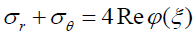
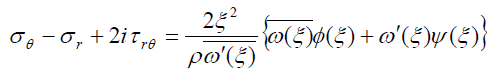
Where  are the stresses acting in the considered point of massif block: radial, tangential, and shearing, respectively; is the real part of display function:
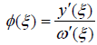
Where  is the function of plane (ξ), onto which the plane of complex variable
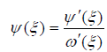
  is displayed; ρ is the dimensionless radius of plane (ξ); ω(ξ) is the displayed function of plane (Z) onto plane (ξ).
The superscript ′ means conjugation.
For dynamic problems the equation of wave propagation in heterogeneous medium is solved.
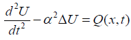
where U is the rock displacement, Δ is the Laplace operator,  for one-dimension medium; Q(x,t) is the force disturbing oscillations and waves per unit length; x, t are the coordinates of oscillations along x axis and in time, respectively.
This equation has initial conditions:
and heterogeneous boundary conditions:
on free surface  on loaded surface of blast hole
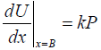
The load P, applied to blast hole walls and being equal to average pressure of explosion products, creates radial (σr) and tangential (σθ) stresses in rocks around blast hole, which are determined using the aforementioned equations. Solution of these equations is as follows:
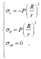
Where are the blast hole radius and distance between the blast hole center to the considered point respectively.
Upon longwall excavation the efficiency is mainly determined by correct selection of blast hole depth, charge weight, and blast hole layout. It is well known that when blasting is carried out in squeezed medium specific consumption of explosive should be additionally increased. It is mentioned by some researchers (Andreev, 2009; Eremenko, et al., 2002; Zhurov, 2007) that upon excavation of rectangular cross section in homogenous elastic isotropic rock massif the zone of longitudinal stress strain is formed in front of hole bottom (εy>0). This zone is propagated from the hole bottom surface deep into massif for the distance depending on transversal cross section of excavation. Herewith, if the coefficient of horizontal stress λ<1 , then the zone size increases; and if λ>1, then it decreases. Analysis of this phenomenon demonstrates that the optimum selection of bore hole depth is not to exceed the seizes of this zone.
As shown by experience of mining in actual conditions, bore hole depths exceed these sizes.
While considering longwall excavation as an integrated blasting operations, it is required to highlight three stages of these operations: cut holes, outer holes, and peripheral holes.
One of the most important property for determination of optimum blasting and drilling parameters upon excavation is the explosion funnel formed as a consequence of blasting of bore holes. This funnel generates the second free face in perpendicular to longwall plane. Existence of the second free face all the way down of outer holes promotes operation of all other bore holes.
When breaking-in charges are blasted, shooting is usually observed in bottom part of blast hole, its value depends on blast hole depth, physicomechanical properties of rocks and type of explosives. Existence of shootings impairs performances of blasting operations.
Zones of overgrinding and rock plastic strains are formed around blasted charge. The sizes of these zones are moderate and depend on rock properties, type of explosives, charge design. Significant portion of shock wave energy is consumed in the overgrinding zone due to dissipative losses. Beyond the boundaries of plastic strains the shock wave is transformed into the strain wave which carries out destruction in the form of micro- and macro-cracks propagating deep into the massif. Mechanism of formation of overgrinding zones and plastic strains for various mining and geological conditions is the same, only radius of these zones varies.
Upon explosion of bore hole charge, located beyond the zone of impact of excavation cross section, the explosion funnel is formed in three stages:
• Stage I - destruction of rock massif in the region of all-round compression. Overgrinding zone is formed around the first cut hole upon charge explosion as a consequence of internal impact. The influence of wave, reflected from bore hole bottom, is negligible due to significant distance of free surface. The generated overgrinding zone influence positively on the blasting of adjacent breaking-in charges.
• Stage II - generation of explosion funnel in the impact zone of maximum compressing stresses. Significant influence on funnel parameters in this zone is exerted by potential energy of static stress field, directed towards free surface, strain rate of rock massif, and energy of reflected wave.
• Stage III - takes place in close vicinity of excavation surface - in active zone of stretching strains. The funnel volume in this region slightly depends on physicomechanical properties of rocks and is stipulated by intensity of rock massif, depth of boundary destruction and amount of explosive charge in bore hole.
In order to determine the radius of destruction, explosion funnel volume and, hence, conditions for its generation at present parameters, it is required to establish their dependence on mining and geological conditions, depth of laying and strength of charge.
On the basis of the aforementioned it is possible to conclude that efficient operation of cut holes should be supported by creation of supercharge in cut holes in order to provide maximum destructions all over its depth and formation of explosion funnel of maximum possible sizes.
Increase in specific consumption in cut holes is not optimum, since under conditions of explosive atmosphere it can increase the chance of its ignition and blasting, and on the other hand it can lead to occurrence of squeezed detonation in adjacent bore holes as well as to increase in excavation expenses.
Another approach to increase efficiency of cut holes is additional increase of fracture zone at quasi-static stage of explosion impact.
In drilled area upon excavation rocks are fractured with various efficiency. At significant distance from excavation rocks are in volumetric stressed state, hence, in order to provide high quality grinding it is necessary not only to maintain the mode of steady and uniform propagation of explosive cracks but to consume additional energy for overcoming of initial stressed state of destructed rock bulk.
Upon explosion of bore hole charge grinding and fracturing zones are formed around explosion chamber at the moment of completion of wave stage of explosion impact. Explosion products in the chamber create stress field in surrounding area. Stress concentration in the crack tips formed at the wave stage of explosion can exceed critical levels, then the conditions of crack growth are developed.
Some researchers (Menzhulin, et al., 2001; Stavrogin and Tarasov, 2001; Shemyakin, 2007; Brown and Thomas, 2000; Khristoforov, 2010) reported about development of induced fracturing and propagation of main cracks for significant distances.
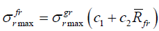
Stress variations for cylindrical charge can be written as follows:
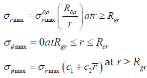
where φmax σ is the radial and tangential stress constituents, respectively, Pa; is the radial stress constituent at the grinding zone boundary, Pa; Rgr, Rcr are the radii of grinding and fracturing zones, respectively, m; c1 and c2 are dimensionless constants, depending on rock acoustic hardness;
  is the relative distance from charge axis, R03 * is the charge radius in PETN equivalent, m.
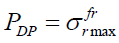
The pressure of detonation products Pdp in explosion chamber with accounting for their decompaction is considered to be equal to radial stress constituent at radius of fracturing zone.
In elastic zone (beyond the fracturing zone) cracks can grow due to stretching stresses, that is, tangential stress constituent should be known:
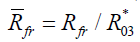
where Rfr is the radius of fracturing zone.
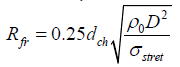
Where ρ0 is the density of explosive, kg/m3; σstret σpacm is the uniaxial stretching ultimate strength, Pa; D is the detonation velocity, m/s; dch is the charge diameter, m.
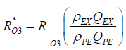
where λ=0.5 for cylindrical charges; R03is the radius of explosive charge; ρEX, ρPE are the density of applied explosive and PETN, respectively; QEX, QPE are the heat of applied explosive and PETN, respectively.
Stress distribution beyond fracturing zone is as follows:
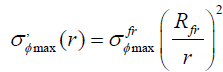
where r is the distance from charge axis, at which the stress acts:
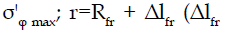 is the length increment of crack which ends at the radius of fracturing zone).
Taking into account the aforementioned, the crack length increment can be expressed as follows:
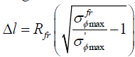
Calculations of radius increment of additional fracturing due to quasi-static impact of explosion products are illustrated in Fig. 1.

Fig. 1 Dynamic flowchart of the vibration gyratory-cone crusher.
Qualitative regularities of fracturing upon explosion of borehole charges of various design were determined in laboratory studies. Organic glass blocks were used as models, where longitudinal speed of sound is ÃÂáÃâÃâ¬=2820 m/s, density ρ=1.18°10-3 kg/m3, Young modulus E =0.53°1010 Pa, Poisson coefficient ν=0.35, sizes: 100*100*100 mm. PETN was used as explosive. The charge was initiated by electric igniter with lead azide. The charge weight was 80 mg to 120 mg. Borehole diameter: 2.5 mm to 3.5 mm.
Formation of main cracks and intensive fracturing zone were studied. Their length, quality and sizes of intensive fracturing zone were determined. Each experimental series included from 3 to 5 tests.
Analysis of experimental results demonstrates that upon explosion of borehole charges two fracturing zones are formed: the zone of strong cracks and the intensive fracturing zone, the crack length in which is about 0.5 length of main crack, and its radius is 0.25 of the same length. Experimental results are summarized in Table 1.
| Charge design | No. | NÃÂÃÅ | lÃÂü, 10-3, m | Ncr | lcr, 10-3, m | Rcr(av), 10-3, m |
|---|---|---|---|---|---|---|
| Solid charge without stemming | 1 | 6 | 52.8-70.4 | 14 | 32 | 19.2 |
| 2 | 5 | 49.2-68.4 | 15 | 30 | 18.6 | |
| 3 | 7 | 50.1-72.0 | 14 | 29 | 17.9 | |
| Solid charge + end-sealed stemming | 1 | 4 | 64-72 | 21 | 50-56 | 38 |
| 2 | 7 | 62-73 | 29 | 48-51 | 40 | |
| 3 | 5 | 58-63 | 24 | 42-46 | 29 | |
| Charge with air deck + end-sealed stemming | 1 | 5 | 52-58 | 10 | 20-25 | 14 |
| 2 | 6 | 60-66 | 12 | 28-38 | 16 | |
| 3 | 5 | 49-56 | 8 | 24-29 | 12 |
Note: where NÃÂÃÅ is the number of main cracks; lÃÂü is the length of main cracks; NCr is the number of cracks in intensive fracture zone; lCr is the length cracks in intensive fracture zone; RCr is the radius of intensive fracture zone
Table 1. Experimental results
In addition, it follows from the analysis that upon explosion of charges with end-sealed stemming in comparison with quartz sand stemming the intensive fracturing radius increases by 50% to 60%, herewith, the length of main cracks increases only by 10% to 15%. Results of explosion of charges with air decks demonstrate that the intensive fracturing radius decrease by 20% to 30%, the length of main cracks remains nearly the same.
Induced fracturing beyond contoured portion of massif upon excavations is determined by the following main parameters: the distance from contour charge to design excavation surface, the distance between charges in contour row, specific consumption with accounting for mining conditions.
Some researchers (Kovazhenkov, 1958; Eremenko, et al., 2000; Mashukov, et al., 2007; Torunov, et al., 2010) reported that under all-round compression the destruction pattern varies significantly. The influence of static pressure on development of fracturing zone upon explosion of charges of various designs was studied in experiments.
The experiments were performed with blocks of organic and quartz glass with the sizes of 100*100*100 mm and 100*80*50 mm. Boreholes, 60 mm in depth and 3 mm in diameter, were drilled in the block center. PETN was used as explosive, the charge weight was 70 mg. The charge was initiated by electric igniter with lead azide. Quartz sand and clay were used as stemming. Prior to explosion the samples were loaded by uniaxial compression. The load was applied by hydraulic press via metal plates and varied in the range from 200 Kg to 2000 kg, which corresponded to from 2 MPa to 20 MPa.
The sizes of destruction zones were determined in the plane perpendicular to axis of charge center, thus eliminating the influence of stabbing.
The experimental results demonstrate that even slight compressing stresses vary sharply the destruction pattern. The shape of intensive fracturing zone (radial and ring fractures) is nearly the same as that of unloaded sample, and the zone of radial cracks (their amount) decreases significantly. Herewith, the length of radial cracks increases along the load axis. Experimental results are summarized in Table 2.
| Pre-compression strain, MPa | Radius of fracture zone *, mm | |||
|---|---|---|---|---|
| Intensive fracturing | Radial fractures | |||
| Charge with sand-clay stemming | Charge with end-sealed stemming | Charge with sand-clay stemming | Charge with end-sealed stemming | |
| 2 | 32.4 | 38.6 | 58.2 | 64.8 |
| 5 | 29.1 | 35.2 | 49.1 | 52.6 |
| 10 | 27.0 | 34.1 | 38.2 | 48.2 |
| 15 | 25.5 | 33.4 | 36.1 | 47.4 |
| 20 | 24.5 | 32.1 | 35.2 | 46.2 |
Note*-the average value with respect to 5 experiments
Table 2. Experimental results
Mechanism of rock destruction by charge explosion is sufficiently complex, since the destruction occurs in very short intervals at sufficiently high values of dynamic loads. Therefore, no common point of view on rock destruction by explosion has been developed up till now. Numerous researchers tried to discover physical essence of medium deformation by explosion, energy parameters of this process and methods of its monitoring. However, the obtained results are different and often controversial.
The performed studies differ in terms of approach to explosion impact on rock massif. These are mainly three trends based on hydrodynamics, wave theory, and hypotheses of two constituents of stress field.
Explosion is the process of high-speed dynamic loading of rocks. However, the rock loading pattern and resulting deformations of massif are interpreted in different ways. From the point of view of hydrodynamics and theory of shock waves the explosion dynamic loading is considered as single peak pulse pressure acting in predetermined interval. The concept of two constituents of stress field assumes the existence of initial shock load, and quasi-static load slowly varying in time. The loading pattern and applied destruction criteria are different in each approach.
At present numerous researchers believe that the transfer of explosion energy to environment cannot be constrained by shock wave. It is assumed that detonation of explosive has pulsating pattern. Seismographic and acoustic instrumentation installed at various distance from explosion records not a single peak pulse of shock wave but a cycle of harmonic sinusoidal oscillations, moreover, seismic sensors record a series of low amplitude oscillation and subsequent oscillations with higher amplitude and not the reverse. In this case rock loading upon explosion is a dynamic pulsating oscillating process with comparatively low amount of active loading cycles. Rock destruction mechanism by explosion can be considered in terms of low-cycle fatigue of rock materials with comparatively low ultimate tensile strength. On the basis of these studies (Vovk, 1985) proposed hypothesis of two constituents of stress field near charge: high-frequency, corresponding to wave front, and long-period, stipulated by quasistatic load resulting from impact of detonation products of explosive.
The presented overview of main concepts of rock destruction mechanism demonstrates that the concepts vary noticeably depending on accepted by authors initial factor of rock destruction prior to explosion.
Nowadays underground mining operations are based mainly on dynamic excavations using explosives in contoured boreholes.
It is experimentally established that upon explosion of low-strength substances in perimeter charges the radius of intensive fracturing decreases by 30% to 40%, herewith, the growth of main crack and its dimensions with regard to scheduled explosion are reduced by 10%.
Formation and propagation of main cracks and fracture zones have been experimentally studied as a function of properties of explosives and charge design at quasi-static stage of explosion impact. The experimental results demonstrate that the relative radius of charges without stemming equals to 0.96, and that of charges with sand-clay and shaped stemming equals to 0.97 and 0.985 respectively.
Copyright © 2025 Research and Reviews, All Rights Reserved